
The ISO designation system (ISO 1832) standardizes the naming of indexable inserts, representing each important feature and dimension using a code system. This unique code becomes the insert’s name.
Unique naming of indexable inserts, independent of the supplier. Clear inclusion of all important features and dimensions in the name. Some code positions correspond to the insert carrier for mounting.
It’s important to note that the ISO designation system does not standardize the quality of the insert, including the carbide grade or cutting geometry.
① Insert shape
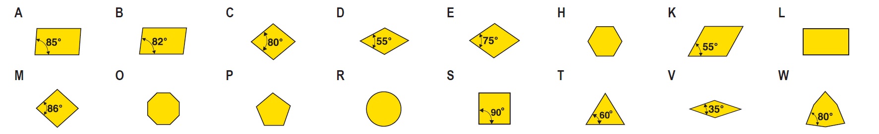
X – Special shapes Z – Special shapes
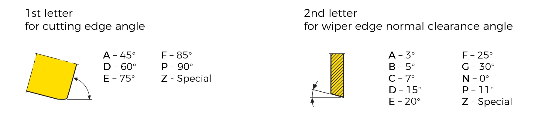
② Normal clearance angle
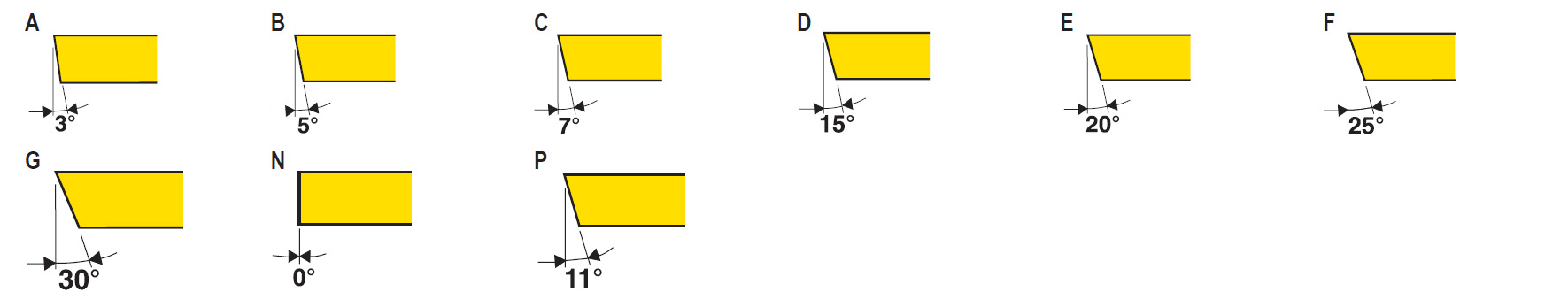
O – Special shapes
③ Tolerance class
| Insert Shape ① | For Diameter of IC | Class | Tolerance in mm | Tolerance in Inch | |||||
| mm | Inch | Inscribed Circle IC | Corner Height M | Thickness S | Inscribed Circle IC | Corner Height M | Thickness S | ||
| All shapes | 4.76-32 | 3/16-1 1/4 | A | ± 0.025 | ± 0.005 | ± 0.025 | ± 0.0010 | ± 0.0002 | ± 0.0010 |
| All shapes | 4.76-32 | 3/16-1 1/4 | C | ± 0.025 | ± 0.013 | ± 0.025 | ± 0.0010 | ± 0.0005 | ± 0.0010 |
| All shapes | 4.76-32 | 3/16-1 1/4 | E | ± 0.025 | ± 0.025 | ± 0.025 | ± 0.0010 | ± 0.0010 | ± 0.0010 |
| All shapes | 4.76-32 | 3/16-1 1/4 | F | ± 0.013 | ± 0.005 | ± 0.025 | ± 0.0005 | ± 0.0002 | ± 0.0010 |
| All shapes | 4.76-32 | 3/16-1 1/4 | G | ± 0.025 | ± 0.025 | ± 0.130 | ± 0.0010 | ± 0.0010 | ± 0.0050 |
| All shapes | 4.76-32 | 3/16-1 1/4 | H | ± 0.013 | ± 0.013 | ± 0.025 | ± 0.0005 | ± 0.0005 | ± 0.0010 |
| All shapes | 4.76-10 | 3/16-3/8 | J | ± 0.050 | ± 0.005 | ± 0.025 | ± 0.0020 | ± 0.0002 | ± 0.0010 |
| All shapes | 12-12.7 | 1/2 | ± 0.080 | ± 0.005 | ± 0.025 | ± 0.0030 | ± 0.0002 | ± 0.0010 | |
| All shapes | 15.875-20 | 5/8-3/4 | ± 0.100 | ± 0.005 | ± 0.025 | ± 0.0040 | ± 0.0002 | ± 0.0010 | |
| All shapes | 25-25.4 | 1 | ± 0.130 | ± 0.005 | ± 0.025 | ± 0.0050 | ± 0.0002 | ± 0.0010 | |
| All shapes | 31.75-32 | 1 1/4 | ± 0.150 | ± 0.005 | ± 0.025 | ± 0.0060 | ± 0.0002 | ± 0.0010 | |
| All shapes | 4.76-10 | 3/16-3/8 | K | ± 0.050 | ± 0.013 | ± 0.025 | ± 0.0020 | ± 0.0005 | ± 0.0010 |
| All shapes | 12-12.7 | 1/2 | ± 0.080 | ± 0.013 | ± 0.025 | ± 0.0030 | ± 0.0005 | ± 0.0010 | |
| All shapes | 15.875-20 | 5/8-3/4 | ± 0.100 | ± 0.013 | ± 0.025 | ± 0.0040 | ± 0.0005 | ± 0.0010 | |
| All shapes | 25-25.4 | 1 | ± 0.130 | ± 0.013 | ± 0.025 | ± 0.0050 | ± 0.0005 | ± 0.0010 | |
| All shapes | 31.75-32 | 1 1/4 | ± 0.150 | ± 0.013 | ± 0.025 | ± 0.0060 | ± 0.0005 | ± 0.0010 | |
| All shapes | 4.76-10 | 3/16-3/8 | L | ± 0.050 | ± 0.025 | ± 0.025 | ± 0.0020 | ± 0.0010 | ± 0.0010 |
| All shapes | 12-12.7 | 1/2 | ± 0.080 | ± 0.025 | ± 0.025 | ± 0.0030 | ± 0.0010 | ± 0.0010 | |
| All shapes | 15.875-20 | 5/8-3/4 | ± 0.100 | ± 0.025 | ± 0.025 | ± 0.0040 | ± 0.0010 | ± 0.0010 | |
| All shapes | 25-25.4 | 1 | ± 0.130 | ± 0.025 | ± 0.025 | ± 0.0050 | ± 0.0010 | ± 0.0010 | |
| All shapes | 31.75-32 | 1 1/4 | ± 0.150 | ± 0.025 | ± 0.025 | ± 0.0060 | ± 0.0010 | ± 0.0010 | |
| Other shapes | 4.76-10 | 3/16-3/8 | M | ± 0.050 | ± 0.080 | ± 0.013 | ± 0.0020 | ± 0.0030 | ± 0.0050 |
| D | ± 0.050 | ± 0.110 | ± 0.013 | ± 0.0020 | ± 0.0040 | ± 0.0050 | |||
| V | ± 0.050 | ± 0.160 | ± 0.013 | ± 0.0020 | ± 0.0060 | ± 0.0050 | |||
| Other shapes | 12-12.7 | 1/2 | ± 0.080 | ± 0.130 | ± 0.013 | ± 0.0030 | ± 0.0050 | ± 0.0050 | |
| D | ± 0.080 | ± 0.150 | ± 0.013 | ± 0.0030 | ± 0.0060 | ± 0.0050 | |||
| V | ± 0.080 | ± 0.250 | ± 0.013 | ± 0.0030 | ± 0.0100 | ± 0.0050 | |||
| Other shapes | 15.875-20 | 5/8-3/4 | ± 0.100 | ± 0.150 | ± 0.013 | ± 0.0040 | ± 0.0060 | ± 0.0050 | |
| D | ± 0.100 | ± 0.180 | ± 0.013 | ± 0.0040 | ± 0.0070 | ± 0.0050 | |||
| All shapes | 25-25.4 | 1 | ± 0.130 | ± 0.180 | ± 0.013 | ± 0.0050 | ± 0.0070 | ± 0.0050 | |
| All shapes | 31.75-32 | 1 1/4 | ± 0.150 | ± 0.200 | ± 0.013 | ± 0.0060 | ± 0.0080 | ± 0.0050 | |
| Other shapes | 4.76-10 | 3/16-3/8 | N | ± 0.050 | ± 0.080 | ± 0.025 | ± 0.0020 | ± 0.0030 | ± 0.0010 |
| D | ± 0.050 | ± 0.110 | ± 0.025 | ± 0.0020 | ± 0.0040 | ± 0.0010 | |||
| V | ± 0.050 | ± 0.160 | ± 0.025 | ± 0.0020 | ± 0.0060 | ± 0.0010 | |||
| Other shapes | 12-12.7 | 1/2 | ± 0.080 | ± 0.130 | ± 0.025 | ± 0.0030 | ± 0.0050 | ± 0.0010 | |
| D | ± 0.080 | ± 0.150 | ± 0.025 | ± 0.0030 | ± 0.0060 | ± 0.0010 | |||
| V | ± 0.080 | ± 0.250 | ± 0.025 | ± 0.0030 | ± 0.0100 | ± 0.0010 | |||
| Other shapes | 15.875-20 | 5/8-3/4 | ± 0.100 | ± 0.150 | ± 0.025 | ± 0.0040 | ± 0.0060 | ± 0.0010 | |
| D | ± 0.100 | ± 0.180 | ± 0.025 | ± 0.0040 | ± 0.0070 | ± 0.0010 | |||
| All shapes | 25-25.4 | 1 | ± 0.130 | ± 0.180 | ± 0.025 | ± 0.0050 | ± 0.0070 | ± 0.0010 | |
| All shapes | 31.75-32 | 1 1/4 | ± 0.150 | ± 0.200 | ± 0.025 | ± 0.0060 | ± 0.0080 | ± 0.0010 | |
| All shapes | 4.76-10 | 3/16-3/8 | U | ± 0.080 | ± 0.130 | ± 0.013 | ± 0.0030 | ± 0.0050 | ± 0.0050 |
| All shapes | 12-12.7 | 1/2 | ± 0.130 | ± 0.200 | ± 0.013 | ± 0.0050 | ± 0.0080 | ± 0.0050 | |
| All shapes | 15.875-20 | 5/8-3/4 | ± 0.180 | ± 0.270 | ± 0.013 | ± 0.0070 | ± 0.0110 | ± 0.0050 | |
| All shapes | 25-25.4 | 1 | ± 0.250 | ± 0.380 | ± 0.013 | ± 0.0100 | ± 0.0150 | ± 0.0050 | |
| All shapes | 31.75-32 | 1 1/4 | ± 0.250 | ± 0.380 | ± 0.013 | ± 0.0100 | ± 0.0150 | ± 0.0050 | |
④ Fixing and / or chipbreaker
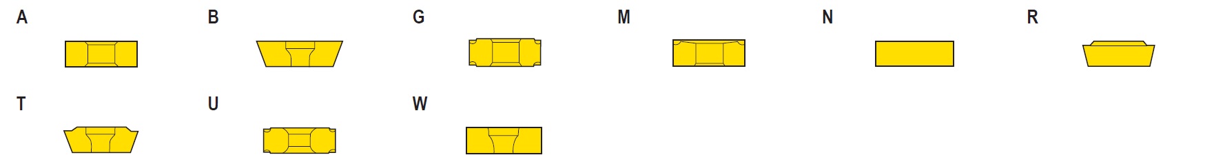
X – Special shapes Z – Special shapes
⑤ Cutting edge length

Equilateral inserts
Metric system
Choose the value of the side length as the symbol of designation and disregard and decimals. If the resulting symbol has only one digit, it shall be preceded by 0 (zero).
EXAMPLE
Edge length: 15.5 mm Symbol of designation: 15
Edge length: 9.525 mm Symbol of designation: 09
Inch system
Choose the value of the inscribed circle as the symbol of designation. The symbol is the numerator of the fraction measured in 1/8 inch.
a) It is a one-digit symbol when the numerator is a whole number.
EXAMPLE
Diameter of inscribed circle: 1/2 inch Symbol of designation: 4 (1/2 = 4/8)
b) It is a two-digit symbol when the numerator is not a whole number.
EXAMPLE
Diameter of inscribed circle: 5/16 inch Symbol of designation: 2,5 (5/16 = 2.5/8)
Non-equilateral inserts
The symbol designation for the insert size is always given for the major cutting edge or the longer cutting edge. The indication of other dimensions shall be made by means of a sketch or detailed explanation, indicated at position 4 by the symbol X.
Metric system
The symbol of designation is the length, disregarding and decimals.
EXAMPLE
Length of the main edge: 19.5 mm Symbol of designation: 19
Inch system
The symbol of designation is numerator of the fraction for the value in 1/4 inch.
EXAMPLE
Length of the main edge: 3/4 inch Symbol of designation: 3
Round inserts
Metric system
Choose the value of the diameter as the symbol of designation and disregarding and decimals.
EXAMPLE
Insert diameter: 15.875 mm Symbol of designation: 15
For inserts having rounded metric diameters, the same rule is valid, combined with a special symbol at reference ⑦.
Inch system
Proceed as for equilateral inserts.
⑥ Insert thickness

Rounded or chamfered cutting edge are considered sharp cutting edge.
Metric system
Take the numerical value of the thickness as the symbol of designation for the insert thickness, disregarding any decimals. If the resulting symbol has only one digit, it shall be preceded by 0 (zero).
EXAMPLE
Insert thickness: 3.18 mm Symbol of dsignation: 03
As an exception for inserts having thickness 1.98 mm and 3.97 mm, in order to distinguish them from those having thickness of 1.59 mm (symbol 01) and 3.18 mm (symbol 03), precede the digit by the letter T.
EXAMPLE
Inser thickness: 3.97 mm Symbol of designation: T3
Inch system
The symbol of designation for insert thickness is the numerator of the fraction measured in 1/16 inch.
a) It is a one-digit symbol when the numerator is a whole number.
EXAMPLE
Insert thickness: 1/8 inch Symbol of designation: 2 (1/8 = 2/16)
b) It is a two-digit symbol when the numerator is not a whole number.
EXAMPLE
Insert thickness: 3/32 inch Symbol of designation: 1,5 (3/32 = 1.5/16)
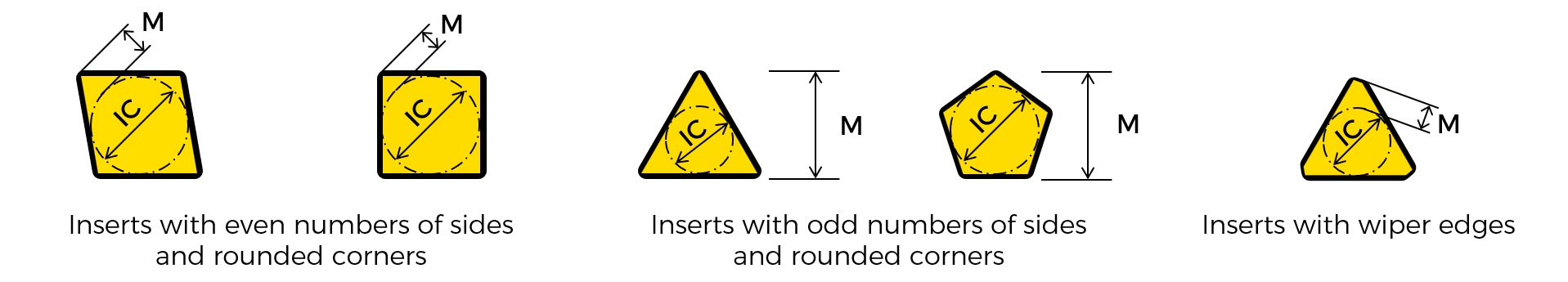
⑦ Corner configuration
The inserts have rounded corners.
Metric system
The symbol of designation is represented by the value of the corner radius given in 0.1 mm. If the number is less than 1, It should be presented by 0 (zero).
EXAMPLE
Corner radius: 0.8 mm Symbol of designation: 08
If the corner is not rounded, use the symbol of designation 00 (zero-zero).
Inch system
The symbol of designation is represented by the following figures:
0 – Sharp corner (not rounded)
1 – Corner redius 1/64 inch
2 – Corner redius 1/32 inch
3 – Corner redius 3/64 inch
4 – Corner redius 1/16 inch
6 – Corner redius 3/32 inch
8 – Corner redius 1/8 inch
X – Any other corner redius
The inserts have wiper edges.
The symbol of designation is represented by the following figures:
To supplement the designation for round inserts, metric system shall indicate:
– 00 (zero-zero) if the diameter is converted from an inch value;
– M0 (M-zero) if the diameter is a metric one.
⑧ Cutting edge condition – Optional symbols
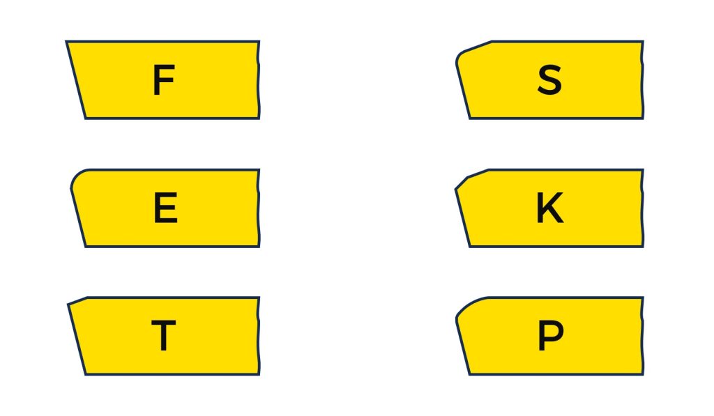
F – Sharp cutting edges
E – Rounded cutting edges
T – Chamfered cutting edges
S – Chamfered and rounded cutting edges
K – Double chamfered cutting edges
P – Double chamfered and rounded cutting edges
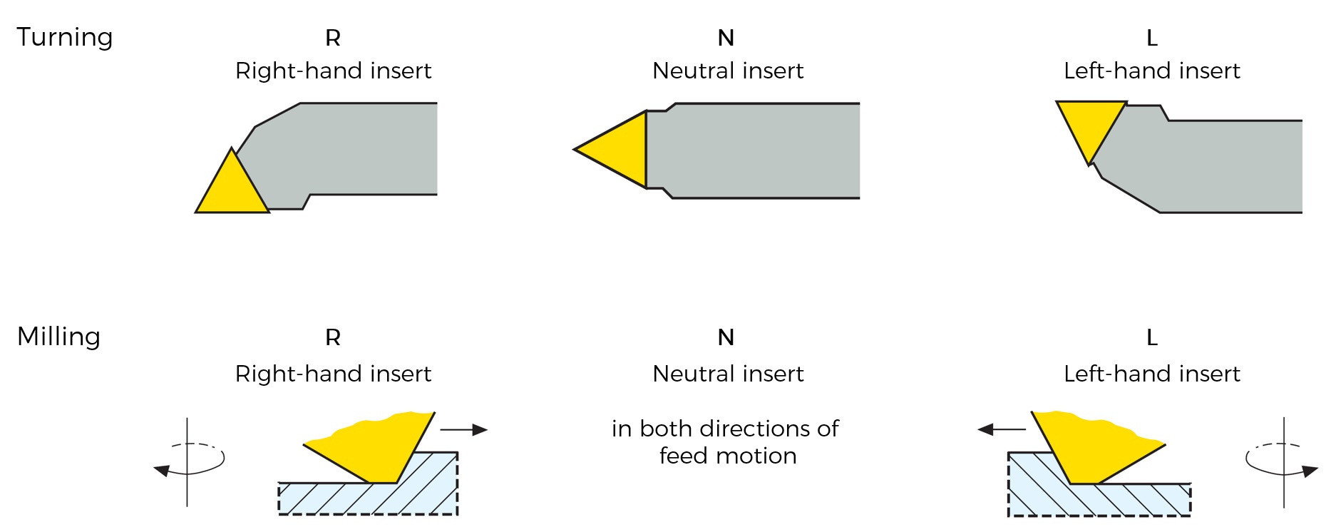
⑨ Direction of feed motion – Optional symbols
⑩ Size of cutting edge condition – Additional symbols for tipped inserts
The maximum allowable shall be a five-digit number symbol( (Three-digit number symbol: T-land size in 1/100 mm. Two-digit number symbol: T-land angle.), depending on the cutting edge condition.
E – Rounded (EXAMPLE: E)
T – Chamfered (EXAMPLE: T05020)
S – Chamfered and rounded (EXAMPLE: S05020)
K – Double chamfered (EXAMPLE: K15010)
P – Double chamfered and rounded (EXAMPLE: P15010)
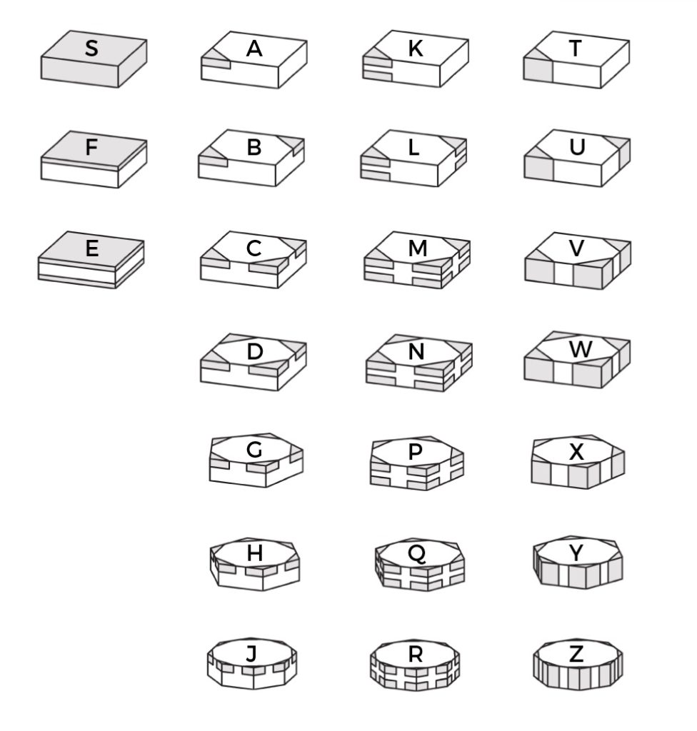
⑪ Style of tipped or solid cutting edge and number of tipped corners – Additional symbols for tipped inserts
The one-digit letter symbol.
S – Solid
F – Full face (one sided)
E – Full face (two sided)
A – Tipped (one sided)(one corner)
B – Tipped (one sided)(two corners)
C – Tipped (one sided)(three corners)
D – Tipped (one sided)(four corners)
G – Tipped (one sided)(five corners)
H – Tipped (one sided)(six corners)
J – Tipped (one sided)(eight corners)
K – Tipped (two sided)(one corner)
L – Tipped (two sided)(two corners)
M – Tipped (two sided)(three corners)
N – Tipped (two sided)(four corners)
P – Tipped (two sided)(five corners)
Q – Tipped (two sided)(six corners)
R – Tipped (two sided)(eight corners)
T – Tipped (full thickness)(one corner)
U – Tipped (full thickness)(two corners)
V – Tipped (full thickness)(three corners)
W – Tipped (full thickness)(four corners)
X – Tipped (full thickness)(five corners)
Y – Tipped (full thickness)(six corners)
Z – Tipped (full thickness)(eight corners)
⑫ length of tipped cutting edge – Additional symbols for tipped inserts
For the one-digit letter symbol:
L – Long
S – Short
F – Full cutting edge length
Cutting edge length given in ISO 16462 and ISO 16463.
Letter symbols L & S
– may appear on letter symbols ⑪ A, B, C, D, G, H, J, K, L, M, N, P, Q, R, T, U, V, W, X, Y, Z.
– cutting edge length is according to standard length.
Letter symbol F
– may appear on letter symbols ⑪ A, B, K, L, T, U, S, F, E.
For the three-digit number symbol:
If the tip length is not full cutting edge or in conformity with the standard length, the effective tip length shall be indicate as a three-digit number symbol which gives the length in 1/10 mm. If the tip length is less than 10.0 mm, the symbol shall be prefixed by zero(s)(0)(e.g. tipped cutting edge length 4.5 mm = 045. tipped cutting edge length 10.7 mm = 107).
EXAMPLE
SNMA150608S05020-BL
Insert with 90° included angles (S), normal clearance angle 0° (N), tolerance class (M), with cylindrical fixing hole and no chip breakers (A), cutting edge length 15.875 mm (15), insert thickness 6.35 mm (06), corner radius 0.8 mm (08), cutting edge condition chamfered and rounded (S), T-land size 0.5 mm (050), T-land angle 20° (20), tipped on one side with two corners (B), tip length 3.0 mm (L).
EXAMPLE
SNMA150608S05020-B045
Insert with 90° included angles (S), normal clearance angle 0° (N), tolerance class (M), with cylindrical fixing hole and no chip breakers (A), cutting edge length 15.875 mm (15), insert thickness 6.35 mm (06), corner radius 0.8 mm (08), cutting edge condition chamfered and rounded (S), T-land size 0.5 mm (050), T-land angle 20° (20), tipped on one side with two corners (B), tip length 4.5 mm (045).
⑬ Chipbreaker – Manufacturer designation
Manufacturer designation for insert chipbreaker types.
⑭ Insert grade – Manufacturer designation
Manufacturer designation for insert grades.