
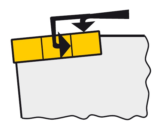
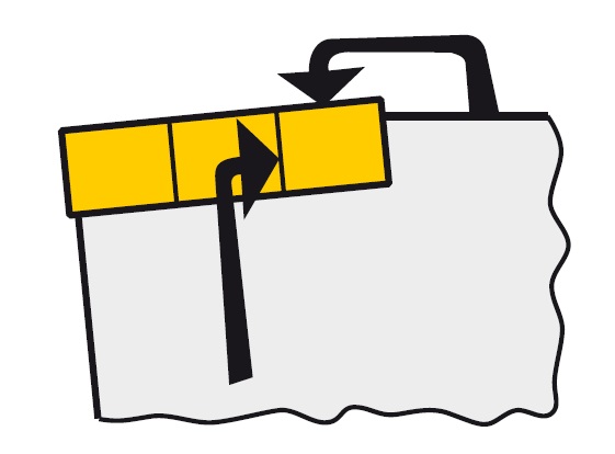
① Insert clamping
C
clamp on top of insert

D
clamp on top of insert and into hole
M
top and through hole clamping
P
clamp with pin through hole

S
clamp with screw through hole

W – wedge clamping N – clamp into notch of insert
② Insert shape
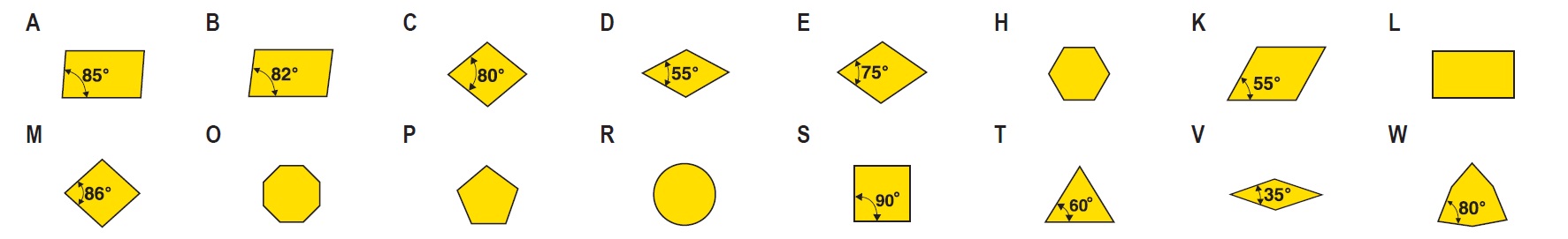
X – Special shapes Z – Special shapes
③ Tool type (approach angle)
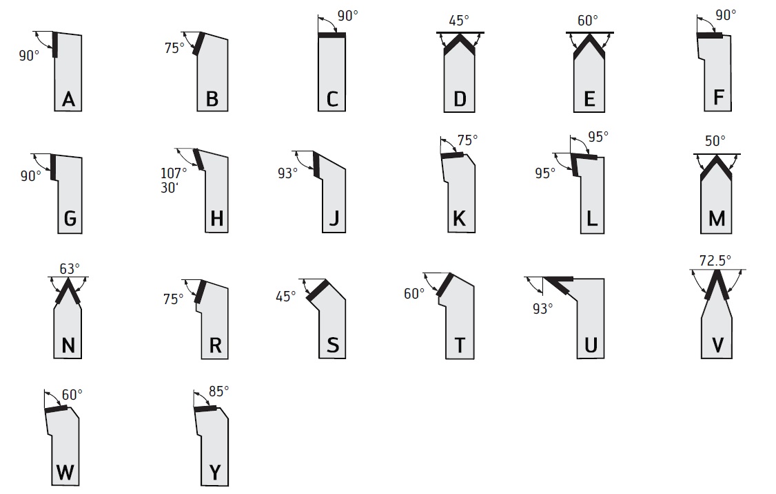
X – Approach angles not specified in the standard.
Special information required.
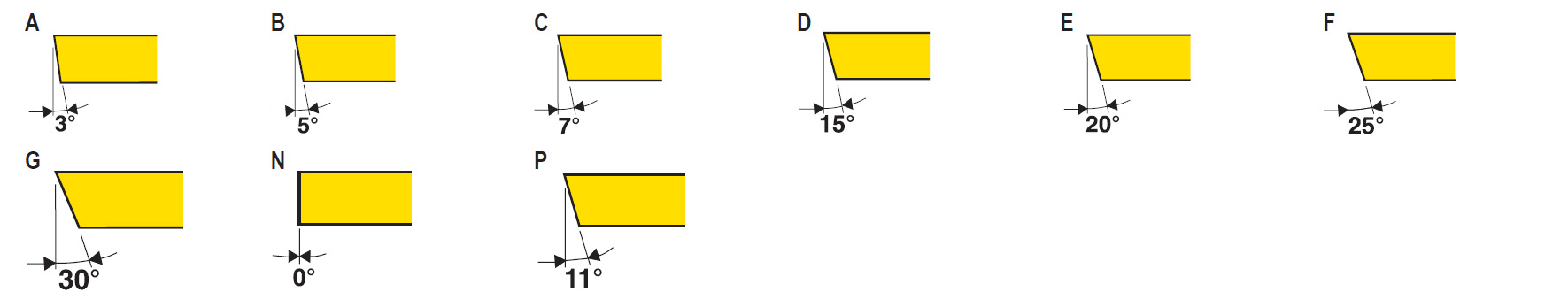
④ Insert normal clearance angle
O – Special shapes
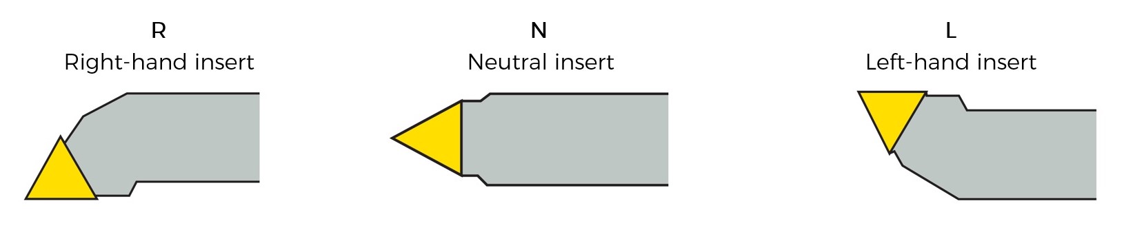
⑤ Cutting direction
⑥ Shank hight
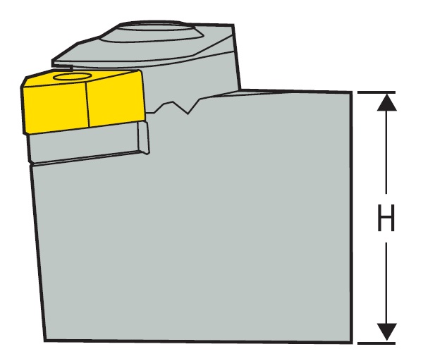
Integers to be preceded by 0
e.g.
08: H = 8 mm
12: H = 12 mm
20: H = 20 mm
25: H = 25 mm
32: H = 32 mm
etc.
⑦ Shank width
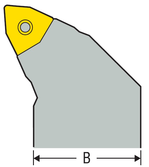
Integers to be preceded by 0
e.g.
08: B = 8 mm
12: B = 12 mm
20: B = 20 mm
25: B = 25 mm
32: B = 32 mm
etc.
⑧ Tool length
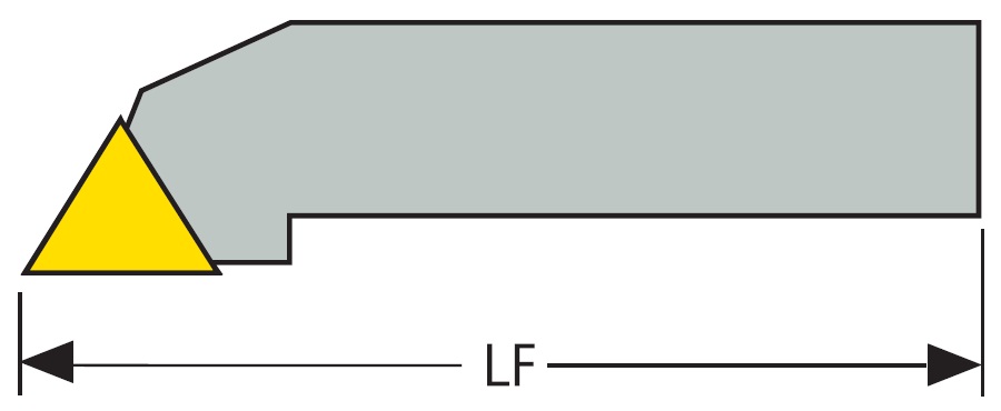
| A = 32 mm | H = 100 mm | Q = 180 mm |
| B = 40 mm | J = 110 mm | R = 200 mm |
| C = 50 mm | K = 125 mm | S = 250 mm |
| D = 60 mm | L = 140 mm | T = 300 mm |
| E = 70 mm | M = 150 mm | U = 350 mm |
| F = 80 mm | N = 160 mm | V = 400 mm |
| G = 80 mm | P = 170 mm | W = 400 mm |
| X = Special |
⑨ Cutting edge length

⑩ Manufacturer’s option
When required a supplementary symbol of letters may be added to the ISO code, separated by a dash, e.g. W for wedge design.