
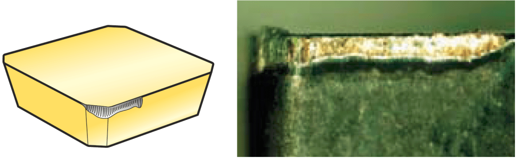
Flank wear is the most desirable wear mode.
Flank wear is a type of abrasive wear caused by the friction between the workpiece material and the back face of the cutting tool. It starts from the cutting edge and gradually progresses downwards.
In the initial stages, flank wear may not be visible to the naked eye and requires magnification using a microscope or loupe. As a rough estimation, one can scrape their fingernail using the cutting edge and compare the tactile difference between a new and worn tool.
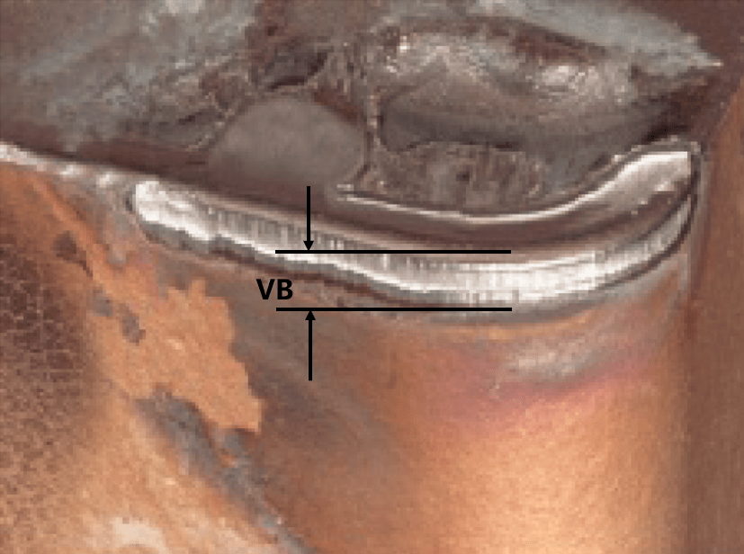
As flank wear intensifies, it leads to increased cutting loads and reduction in tool dimensions. This is one of the primary factors affecting the surface roughness and dimensional accuracy of the machined workpiece.
Wear can be determined by measuring the width of the flank wear land, denoted as VB.
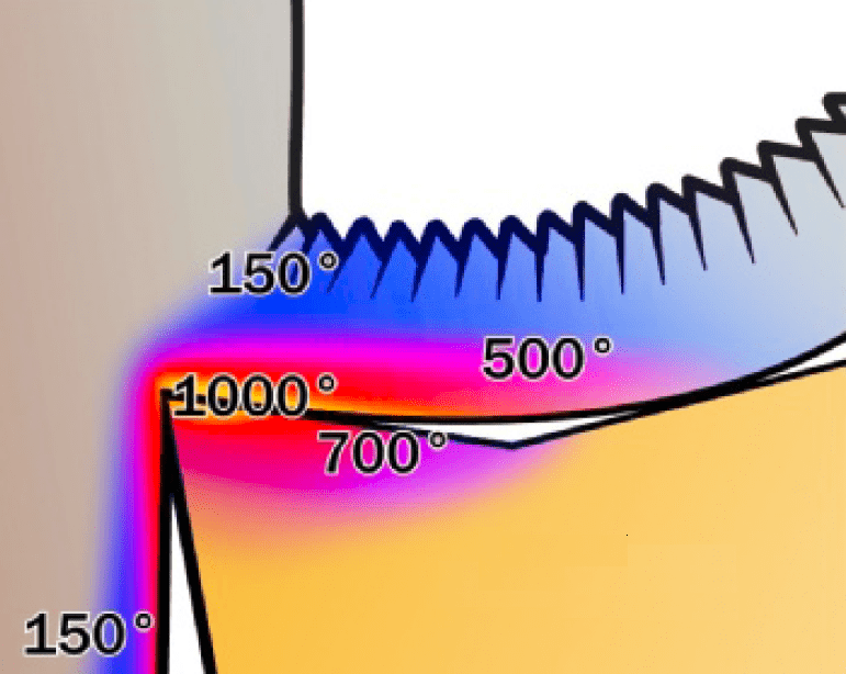
Flank wear primarily tests the material (substrate and coating) of the cutting tool, specifically their wear resistance against the workpiece material at higher cutting temperatures, known as the tool’s red hardness. Therefore, cutting temperature and tool hardness are key factors in this type of wear.
Because flank wear develops steadily and is easily predictable, it is generally desired for the tool to wear in this manner until it reaches failure. However, excessively rapid flank wear is also a problem that needs to be addressed.
Key Factors
Cutting Heat
Mainly related to cutting speed and workpiece material.
Cutting speed is the primary factor in generating cutting heat.
Generally, materials with higher machining strength generate more cutting heat.
Tool Material Red Hardness
The ability of the tool material to maintain sufficient hardness at a certain cutting temperature.
Tip Radius and Insert Volume
The tip radius and size of the tool determine the rate at which cutting heat is transferred from the cutting edge to the tool body.
Coolant
The type, quantity, and delivery method of the coolant directly affect the heat in the cutting zone.
Improvement
Choose more wear-resistant tool materials:
Maintain tool hardness at high cutting temperatures.
Reduce cutting speed:
To lower the temperature in the cutting zone and improve tool wear resistance.
If the cutting efficiency needs to be maintained, compensating by increasing the feed rate can be considered.
Select a larger tip radius or larger tool volume:
To increase the heat dissipation capacity in the cutting zone and reduce heat accumulation at the cutting edge.
Ensure adequate cooling supply:
Directly reduce the temperature in the cutting zone, increase the coolant supply, and target the cutting area.In addition to traditional methods like water cooling and oil cooling, there are also options available such as cooling air, high-pressure cooling, and oil mist cooling.
Improve chip removal:
Carry away more cutting heat through the chips.